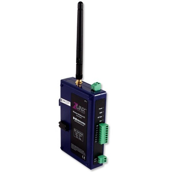
Zlinx ZZ Serie - Wireless I/O zu Modbus System

Die Zlinx ZZ Series von B+B SmartWorx sind Remote I/O zu Modbus Systeme.
Die seriellen Wireless I/O zu Modbus Systeme der Zlink ZZ Serie von B+B SmartWorx sind ausgestattet mit 868MHz oder 900MHz für Long-Range oder 2.4GHz für Short-Range Kommunikation. Außerdem unterstützen sie Point to Point/Multipoint und haben bis zu jeweils 4 digitale Ein- & Ausgänge. Zusätzlich gibt es Modelle die analoge und digitale I/Os kombinieren.

End of Life » Anfrage Produktnachfolger

zum Merkzettel hinzufügen

Datenblatt zusenden


Zlinx ZZ Wireless I/O zu Modbus System

New Features Include:

  • Improved Latency - Very low I/O latency allows real time control and monitoring.
  • Exception Reporting - In Modbus mode, allows the reporting of possible problems with connected devices.
  • Fail Safe - Allows you to set your I/O to a safe state in the event of a communication failure.
  • Calibration - Calculates correction factors to make I/O values more accurate or to better match a sensor.
  • Communications Failure Alarm - Allows the first DO to be configured as a COM failure alarm indicator.
  • Peer-to-Peer I/O Configuration - One to one I/O mapping of 2 identical systems. Allows remote control of analog and digital I/Os.
  • Inverter Outputs - Allows flexibility in the logic to control output devices.
  • Monitor - You can use the Zlinx Manager Software to monitor your I/O.Add Wireless I/O to Any Modbus System

Modbus Appliction (Peer to Multi-Peer)

Seamlessly add wireless I/O to any Modbus application. Modbus is the most widely supported I/O protocol worldwide for PLC's to HMI's and PC based software applications. With Zlinx Wireless I/O you can now bring wireless remote I/O into any Modbus system. Simply connect a Zlinx modem to an RS-232 or RS-485 port of the Modbus master and it can now poll up to 150 wireless I/O nodes - each node can be configured for 8 to 48 I/O points.

Point to Point Applications

B&B Electronics' cellular modem and wireless I/O products replicate analog or digital signals from a remote location wirelessly. Use a pair of Zlinx Wireless I/O modules to read sensor inputs or control actuators in hard-to-reach locations. Inputs and outputs of the paired Zlinx units will mirror-image each other, making it easy to add wireless I/O to any application.

Specifications

Digital Inputs

  • Voltage Range: 0 to 48 VDC
  • Low Voltage (0): 0.8 V maximum
  • High Voltage (1): 4.0 V minimum
  • Pull Up Current: 38 micro-amps
  • Frequency Input: 2 DI inputs per module Software selectable as frequency counters,0 to 5 KHz range.

Digital Outputs

  • Voltage Range:
    • 10 to 40 VDC (Sourcing)
    • 0 to 48 VDC (Sinking)
    • 40 mA per output

Relay Outputs

  • Number of Relays: 8
  • Type: C -normally open & normally closed
  • Output Connection: 3.5mm removable terminal block (2 per output)
  • Common Connection: 3.5mm removable terminal block
  • Ratings: 250VAC @ 8A, 30VDC @5A (maximum per bank of 4 as grouped on the label)

Radio Properties (SR Models)

  • Frequency: 2.4 GHz
  • Output Power : 100 mW
  • Receiver Sensitivity: -102 dbm
  • Antenna: The included antenna is a 4.25 inch omni-directional with RPSMA connector. (p/n ZZ24D-ANT1)

Radio Properties (2.4 GHz MR Models)

  • Frequency: 2.4 GHz
  • Output Power: 50mW
  • Receiver Sensitivity: 105 dbm @ 9.6K
  • Antenna: The included antenna is a 4.25 inch omni-directional with RPSMA connector. p/n ZZ24D-ANT1

Radio Properties (900 MHz MR Models)

  • Frequency: 900 MHz
  • Output Power: 100 mW
  • Receiver Sensitivity: -100 @ 9.6K
  • Antenna: The included antenna is a 6.5 inch omni-directional with RPSMA connector. p/n ZZ9D-ANT1

LED Indicators

  • Receive Signal Strength:
    • Tri-color – Off = No Signal
    • Red = Weak Signal
    • Yellow = Medium Signal
    • Green = Strong Signal
  • RF Data:
    • Green – Blinks with TD or RD
    • Off = No Data
  • Local Bus Data:
    • Green – Blinks with TD or RD
    • Off = No Data
  • Power:
    • Red – On = Power applied
    • Off = No Power

Analog Inputs and Outputs

  • Ranges: 0 to 10 VDC or 0 to 20 mA ZZ-4AO-2 is an active current source. All others are passive
  • Resolution: 12 Bit
  • Input Accuracy: 0.2% full scale reading typical
  • Output Accuracy: 0.27% full scale reading typical
  • AI Load Resistance: 100 Mega Ohms when configured for voltage input 250 Ohms when configured for current input
  • AO Max Output Current: 1 mA when configured for voltage output.
  • AO Max Load 450 Ohms when configured For current output @ 12V

RTD Inputs

  • Number of RTD: 4
  • Wire Configuration: 2, 3, and 4 wire
  • Type: PT100, PT1000 (Optimized for temperature coefficient of 385 C), Cu10 (Optimized for temperature coefficient of 427 C)
  • Input Connection: 3.5mm removable terminal block (4 per output)
  • Temperature Range:
    • PT100 = (-) 200 to (+) 650 C
    • PT1000 = (-) 200 to (+) 100 C
    • Cu10 = (-) 100 to (+) 260 C
  • Resolution: 0.1C cross at (-) 40 to (+) 80 C
  • Accuracy @ 25 C: (+/-) 0.5 C typical
  • Accuracy (-)40 to (+) 80C (+/-) 2.0 C maximum

Radio Properties (900 MHz LR Models)

  • Frequency: 900 MHz
  • Output Power: 1W
  • Receiver Sensitivity: -100 dbm @ 115.2 K, -110 dbm @ 9.6 K
  • Antenna: The included antenna is a 6.5 inch omni-directional with RPSMA connector p/n ZZ9D-ANT1

Radio Properties (868 MHz LR Models)

  • Frequency: 868 MHz
  • Output Power: 315 mW
  • Receiver Sensitivity: -112 dbm
  • Antenna: The included antenna is a 6.5 inch omni-directional with RPSMA connector p/n ZZ9D-ANT1

Environmental

  • Operating Temperature
    • ZZ-8DO-R -40 to 55°C (-40 to 131°F)
    • All Others -40 to 80°C (-40 to 176°F)
  • Maximum Ambient Air Temp
    • ZZ-8DO-R 55°C (131°F)
    • All Others 80°C (176°F)
  • Storage Temperature -40 to 85°C (-40 to 185°F)
  • Operating Humidity 0 to 95% Non-condensing
  • Enclosure Plastic IP30
  • Mounting 35mm DIN Rail
  • Expansion 1 Base Module supports up to 6 Expansion Modules
  • Dimensions 1.2 x 3.7 x 5.0 in (2.9 x 9.3 x 12.7 cm)
Modelle
ZZ8D-NA-LR Zlinx I/O Base Module 868MHz Long Range Base Module, Sourcing
ZZ8D-NB-LR Zlinx I/O Base Module 868MHz Long Range Base Module, Sourcing
ZZ8D-NC-LR Zlinx I/O Base Module 868MHz Long Range Base Module, Sinking
ZZ8D-ND-LR Zlinx I/O Base Module 868MHz Long Range Base Module, Sinking
ZZ9D-NA-LR Zlinx I/O Base Module 900MHz, 2 Analog Inputs, 2 Analog Outputs, 2 Digital Inputs, 2 Digital Outputs, Long Range, Sourcing
ZZ9D-NA-LR-AU Zlinx I/O Base Module 900MHz Long Range Base Module, Sourcing, Australian
ZZ9D-NB-LR Zlinx I/O Base Module 900MHz, 4 Digital Inputs, 4 Digital Outputs, Long Range, Sourcing
ZZ9D-NC-LR Zlinx I/O Base Module 900MHz, 2 Analog Inputs, 2 Analog Outputs, 2 Digital Inputs, 2 Digital Outputs, Long Range, Sinking
ZZ9D-NC-LR-AU Zlinx I/O Base Module 900MHz Long Range Base Module, Sinking, Australian
ZZ9D-ND-LR Zlinx I/O Base Module 900MHz, 4 Digital Inputs, 4 Digital Outputs, Long Range, Sinking
ZZ9D-ND-LR-AU Zlinx I/O Base Module 900MHz Long Range Base Module, Sinking, Australian
ZZ24D-NA-SR Zlinx I/O Base Module, 2.4GHz, 2 Analog Inputs, 2 Analog Outputs, 2 Digital Inputs, 2 Digital Outputs, Short Range, Sourcing
ZZ24D-NB-SR Zlinx I/O Base Module 2.4GHz, 4 Digital Inputs, 4 Digital Outputs, Short Range, Sourcing
ZZ24D-NC-SR Zlinx I/O Base Module, 2.4GHz, 2 Analog Inputs, 2 Analog Outputs, 2 Digital Inputs, 2 Digital Outputs, Short Range, Sinking
ZZ24D-ND-SR Zlinx I/O Base Module, 2.4GHz, 4 Digital Inputs, 4 Digital Outputs, Short Range, Sinking